I made some progress with the pololu tracking and control project.
To allow for better control, I updated the communication protocol between the desktop program and the robot. The previous version supported a minimal set of commands (stop, forwards, spin left, spin right). This set has been replaced by a tuple of values directly controlling the speed of the left and right motors. This allows us to write a more “ambitious” target following algorithm.
The new heuristic is in two steps, speed and direction. We first determine the distance between the tracked robot and the target, and set the speed component as a proportion to distance (close = slow, far = fast). The direction is calculated in a similar fashion: we turn in the direction of the target, the bigger the angle difference between the current heading of the 3pi and the target, the stronger the turn. This remains a simple algorithm, but I a kind of like the behavior. There is more life to it. The following video illustrates (the white dot represents the position of target, the orange dot represents the position of the tracked 3pi robot).
I was recently working on some boid like procedural animations and I was thinking it would be fun to transpose such a system in the physical space. Theo recently received a collection of 5 pololu 3pi robots, and I decided they would be ideal candidates for such a project.
The 3pi pololu robots are fairly simple, so I figured it would be easier to consider the robots as brainless and blind particles under the control of an all-seeing “smart” desktop computer.
The first problem was remote communication with the 3pi. Thankfully, Theo was kind enough to mount an xbee module on one of the bots. This allows remote communication via a serial port abstraction.
The second problem was vision, the desktop controller needs to know the position of the 3pi. As I wanted to create a test environment quickly I fired up CCV instead of written custom tracking code. This is an open source tracker usually used for multitouch surfaces.
I thought it would be interesting to track the 3pi with Infrared light, this would allow for a overhead projection to be added later without influencing the tracking. I used an IR sensitive ps3 eye webcam and Theo added an infrared led to the 3pi to make it visible to the camera (it’s the led on top of the mast on the 3pi picture). The setup was ready to track and send the position of the 3pi to the main desktop program. Now that I knew the position of the 3pi, it was time to make it find and move to a new arbitrary position (target).
For a first test, I opted for a very naive strategy. The situation is the following:
1. we know the position of the 3pi via tracking but not its orientation (visually tracking the orientation is too big of a problem for this first test).
2. we can control the motors of the 3pi, make it move forwards and turn, but we can’t tell it to move or turn a known distance (for instance you can’t tell it to turn 30 degrees).
However, if we tell the bot to move forwards, and we track the movement, we get a new position, which we can compare to the starting position and transpose as a vector, and now we have a direction.
The next step was to decide for a simple vocabulary of movements for the 3pi. I decided that it could either be moving forwards, or spinning to the right, or spinning to the left or, finally, it could be immobile. The heuristic is then quite simple:
1. move forwards
2. are we close enough to the target to be considered the final position?
if yes
stop all done.
else
are we getting closer to the target?
if yes
continue forwards
else
decide if target is to the left or to the right of 3pi and spin in the corresponding direction, then goto 1
Granted this is very naive, but fine for a proof of concept stage.
I used openframeworks to read the tracking information and to communicate serially (xbee) with the 3pi.
You can see the first result in the following video. On the screen, the white dot represents the target and the blue dot is the tracked position of the 3pi.
As you can see the basic system is in place, but there is still a lot of work to get a more fluid experience : )
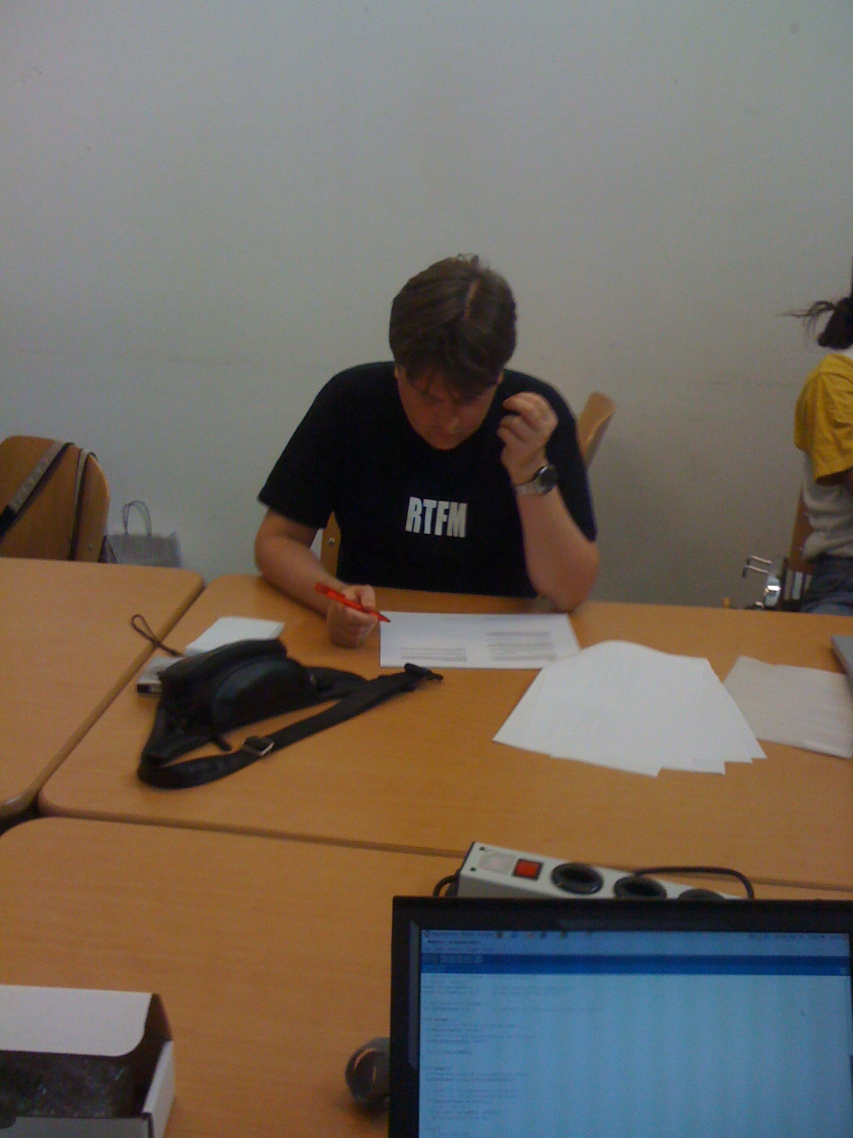
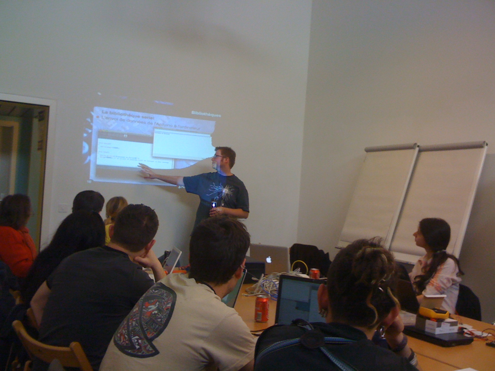
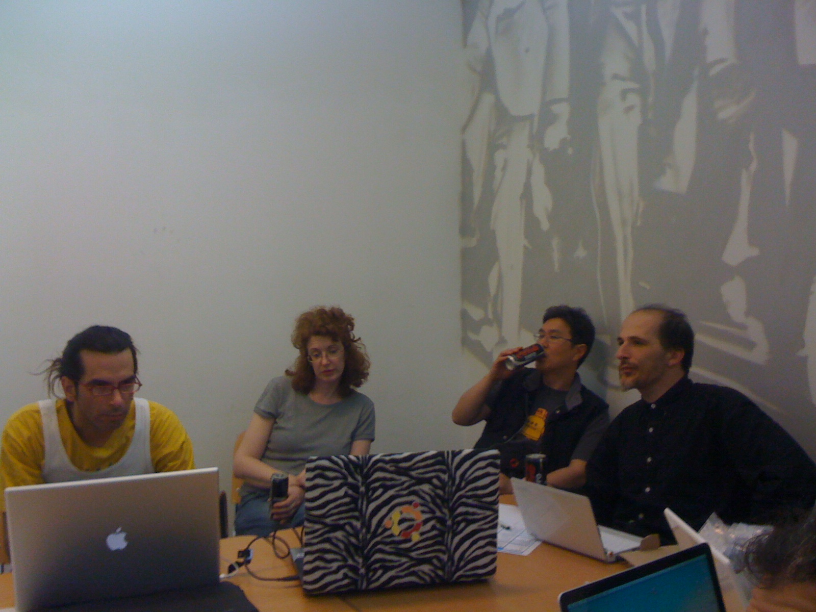
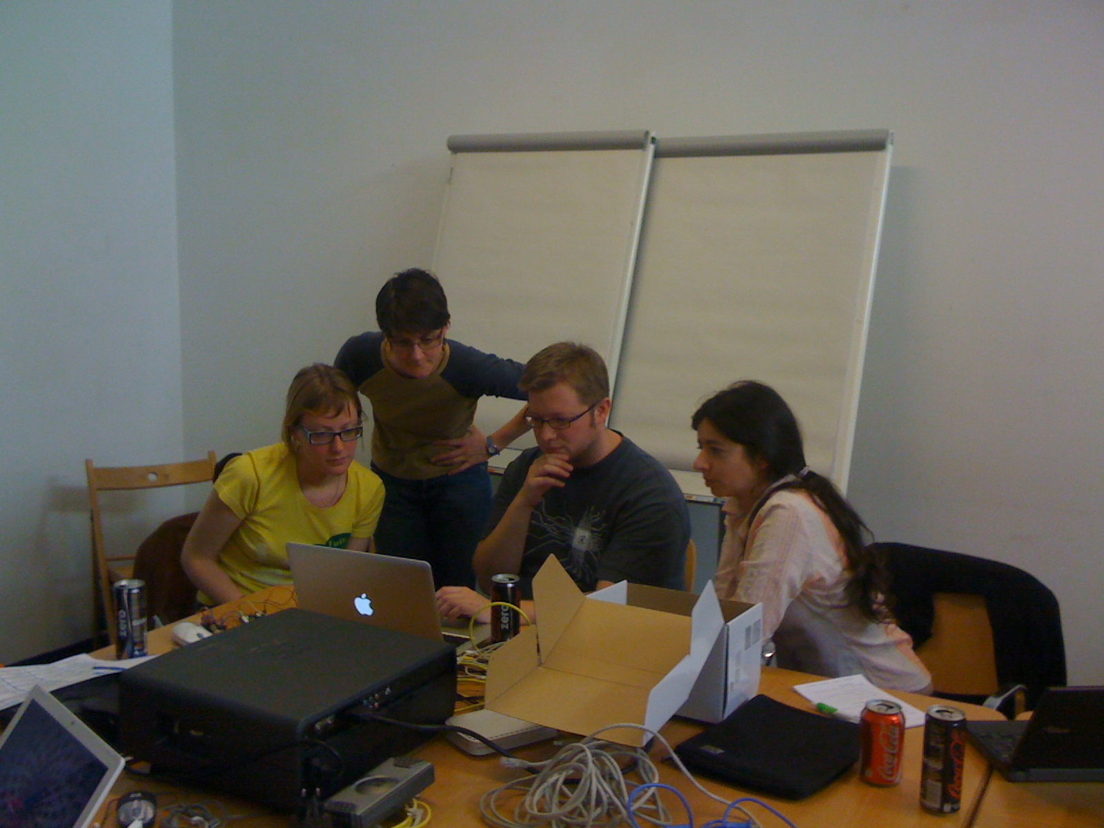
Theo, Julien and myself went to the arduino workshop organised by the guys at post tenebras labs.
The workshop was interesting and fun. It’s always nice to meet fellow geeks : )
Hope we will have another occasion to get together and work on some cool projects.
After printing a sierpinsky triangle on Theo’s makerbot, I thought it might interest some of you to see how I generated the geometry in blender.
However, before starting I should warn you that my knowledge of Blender is virtually non-existent. The blender specific code used here to generate faces is probably not ideal and you’re very welcome to improve that part.
So, what do we want to do? Make triangles, lots of them. We probably need a function to generate triangles. Let’s stay simple and assume that a triangle is composed of 3 points. We are in a 3d space so each point will have 3 components. We shall refer to these points as Vertices. There are many ways to represent this type of data in Python. For something different, let’s try namedtuples. They provide an elegant extension to the base tuple type. They work as follows:
from collections import namedtuple

Vertex = namedtuple('Vertex', 'x, y, z')  # define vertex 'type'

v1 = Vertex(0.0, 0.0, 0.0) # define a Vertex tuple, with positional arguments

v2 = Vertex(x=0.0, y=0.0, z=0.0) #define a Vertex with named arguments

x, y, z = v2    # unpack as regular tupple

x = v.x   # accessible with named parameter
We can now define our triangle function
#import blender bindings
import Blender
from Blender import NMesh
from Blender.BGL import *
from Blender.Draw import *


def triangle(a, b, c):
    """generate triangle geometry
       we expect a b c to be namedtuples of type Vertex"""

    ######### Creates a new mesh
    poly = NMesh.GetRaw()

    ### fill vertices
    v = NMesh.Vert(a.x, a.y, a.z)
    poly.verts.append(v)

    v = NMesh.Vert(b.x, b.y, b.z)
    poly.verts.append(v)

    v = NMesh.Vert(c.x, c.y, c.z)
    poly.verts.append(v)

    ## create a face
    f = NMesh.Face()
    f.v.append(poly.verts[0])
    f.v.append(poly.verts[1])
    f.v.append(poly.verts[2])
    poly.faces.append(f)

     ######### Creates a new Object with the new Mesh
    polyObj = NMesh.PutRaw(poly)

    Blender.Redraw()
My poor knowledge of blender doesn’t allow me to say much about this code. We basically use the api to generate a three point polygon. As said, please improve or correct this part.
Time for a first test!
#define the three vertices of a triangle
a = Vertex(0.0, 0.0, 0.0)
b = Vertex(25.0, 50.0, 0.0)
c = Vertex(50.0, 0.0, 0.0)

triangle(a, b, c)
We define three vertices for our test triangle and call the triangle function. The next step is to load the code in Blender’s text editor and to press Alt-p to run the code.
(sorry for the crappy window in the middle)
Ok, so let’s get to the meat of the problem, i.e. the recursive subdivision. I use the basic algorithm from here, and adapted it to python:
def divideTriangle(a, b, c, step):
    """ recursive divide until step == 0"""

    if step > 0:
        #compute midpoints of sides

        midpointof = lambda v1, v2: Vertex(x = (v1.x + v2.x) * 0.5,
                                           y = (v1.y + v2.y) * 0.5,
                                           z = (v1.z + v2.z) * 0.5)

        ab = midpointof(a, b)
        ac = midpointof(a, c)
        bc = midpointof(b, c)


        # divide all but center triangle

        divideTriangle(a, ab, ac, step - 1)
        divideTriangle(c, ac, bc, step - 1)
        divideTriangle(b, bc, ab, step - 1)
    else:
        #stop recursion and generate geometry
        triangle(a, b, c)
I tried to be as expressive as possible, but I have the feeling that there is something fishy in the midpoint lambda. I guess it could be simplified. But it will do for now. Let’s put it all together, and see what we get in blender.
from collections import namedtuple

import Blender
from Blender import NMesh
from Blender.BGL import *
from Blender.Draw import *


Vertex = namedtuple('Vertex', 'x, y, z')


def triangle(a, b, c):
    """a b c are of type Vertex"""

    ######### Creates a new mesh
    poly = NMesh.GetRaw()

    ### fill vertices

    v = NMesh.Vert(a.x, a.y, a.z)
    poly.verts.append(v)

    v = NMesh.Vert(b.x, b.y, b.z)
    poly.verts.append(v)

    v = NMesh.Vert(c.x, c.y, c.z)
    poly.verts.append(v)

    ## create a face
    f = NMesh.Face()
    f.v.append(poly.verts[0])
    f.v.append(poly.verts[1])
    f.v.append(poly.verts[2])
    poly.faces.append(f)

     ######### Creates a new Object with the new Mesh
    polyObj = NMesh.PutRaw(poly)

    Blender.Redraw()


def divideTriangle(a, b, c, step):
    """ recursive divide until step == 0"""

    if step > 0:
        #compute midpoints of sides

        midpointof = lambda v1, v2: Vertex(x = (v1.x + v2.x) * 0.5,
                                           y = (v1.y + v2.y) * 0.5,
                                           z = (v1.z + v2.z) * 0.5)

        ab = midpointof(a, b)
        ac = midpointof(a, c)
        bc = midpointof(b, c)


        # divide all but center triangle

        divideTriangle(a, ab, ac, step - 1)
        divideTriangle(c, ac, bc, step - 1)
        divideTriangle(b, bc, ab, step - 1)
    else:
        triangle(a, b, c)


#main

a = Vertex(0.0, 0.0, 0.0)
b = Vertex(25.0, 50.0, 0.0)
c = Vertex(50.0, 0.0, 0.0)

divideTriangle(a, b, c, 5)
and in blender: Sierpinsky triangle with 5 levels of subdivision
All done : )
I leave the extruded version as an exercise for the reader.
Playing around with some flocking code (adapted from Daniel Shifman’s implementation ).
I intend to add some controls to the canonical flocking forces (repulsion, align and cohesion) to make the system reactive to external input (multitouch or camera). I also have to think about the rendering, the actual colorama is just for fun.
As we mentioned in a previous post, we relied on the techniques discussed on the Nuigroup site to drive our table (see Nuigroup for specifics). They all use computer vision to solve the multitouch problem. In other words, the position of the fingers on the surface is tracked by camera.
A simple webcam can do the trick. However, it needs to be slightly modified to filter out visible light (so as to avoid capturing the projected image). Then,  via a process of frame differencing and the aid of various thresholding and image processing filters, you obtain a pure black (0) and white image (1) describing the position of the elements in contact with the surface. This is then used as the basis for the tracking.
In our case, we used a modified PS3 eye webcam, which is relatively cheap, and has some excellent frame rates (640×480 at 100fps).
On the software side, we used Tbeta which is an open source tracking solution written with the openframeworks c++ library. Tbeta tracks the elements in contact with the surface and broadcasts their position and id over udp using the Tuio protocol.
Â
tbeta interface
this shows the tbeta interface in action. On the left, the source image from the webcam. On the right the processed B/W Â image used for tracking.