Back then, there was a lot of things to do and I didn’t had my electronic stuff on site, so this movie was never made ( Even if it was not a complicated request : triggering a DSLR from an arduino is really easy, there is even different solutions).
Since then, as a regular hackaday reader, I found a post about a minuscule intervalometer for Canon, Nikon and Pentax cameras developed by Achim Sack.
It is just a small connector with only 3 (three) components. It steals the power from the two signal lines of the camera, and set the interval is as complicated as taking two pictures (read the link if you want more details).
I found this design so elegant, minimal, cheap and convenient to use that I decided to build some for all the people doing photography around me.
I didn’t succeeded in making them fit in the connector body (I didn’t got the same connector than Achim) so I have put heat shrinkable tube around.
It work so well that I had no choice but buy a real DSLR camera 🙂
Time to learn what theses aperture and focal things are about… (you can expect better pictures in my future posts!)
So many thanks to Achim Sack for this work, and if somebody is interested for using one, drop me a mail.
Paul drop by the workshop with two bikes, to solder them together in one bike.
He did it very fast and the result is really funny.
I loved seeing someone so interested by getting a result, doing fast and experiencing its accomplishment right away.
Some work still is required, but yeah, it’s already ridable !
If like me you would like to upload your sketches using the AVRISP mkII under Linux like you can easily do under OSX, I suggest the following procedure:
1. Add the following text to board.txt (located in the relative path hardware/arduino in your arduino installation folder)
2. Backup arduino’s avrdude and use your local avrdude
It seams that the avrdude binary coming with arduino 018 distribution isn’t compiled with usb support.
If your remove it and link your local avrdude binary instead, upload using mkII works like a charm.
# apt-get install avrdude libusb

# cd /path/to/arduino/folder

# cd hardware/tools

# ln -s avrdude avrdude.without-usb-support

# ln -s `type avrdude | cut -d "(" -f 2 | cut -d ")" -f 1` avrdude
Then you will be able to select AVRISP mkII \w ATmega328 or AVRISP mkII \w ATmega168 from the tools>board menu.
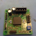
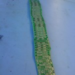
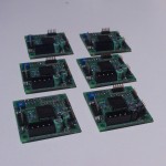
I order PCB for this thing.
It’s a good device, easy to use with any micro-controllers.
There is more than enough, if you drop by our lab I can sell them 10.- each. 50.- with components.
Because I think to power a Makerbot from a car battery, I spend a little while checking the power consumption of a Makerbot.
The main board connector feed the main logic, the plastruder and the heated platform, while the hard drive connectors feed motors and leds.
I used an old ATX connectors and made four groups of wires : 3v3, 5v, 12v and ground.
The remaining wires (5VSB, /PS_ON, PWR_OK, -12v and -5v) where directly connected to the main ATX power supply.
I did the same with hard drive connectors, I disconnected 5v, 12v and ground.
Then I plugged not less than 5 “multimeters” between each power source and ground to record all different current consumption.
So I wrote this sheet :
Voltage
Average
Maximum
MB 3v3
very few
very few
MB 5v
200mA
350mA
MB 12v
2700mA
3500mA
HD 5v
30mA
50mA
HD 12v
1000mA
1700mA
The average power consumption of a makerbot with heating platform seams to be around 70W and the maximum power consumption around 85W. Differences may apply due to the custom configuration, it’s just an overview.
Tonight a friend came with her brand new Mac and a lot of files to import using XDCAM Transfert.
It seams that this software was made by tired developers, so we had to generate previews on every clip before importing.
Well, the real problem isn’t that you have to select the folder, but the fact that you have wait about one second for previews generation (no, there is no “group function”).
With about 3’500 folder, we would have been quickly mad.
And of course, moving all files in one folder isn’t possible, because they already are sorted.
There is probably many other (programmatic and smarter) solutions, but the punk-ier still is the funn-ier, no ?
So my solution is to recycle an old project, writing this post and going for a nice diner, while the mechanism goes by it-self…
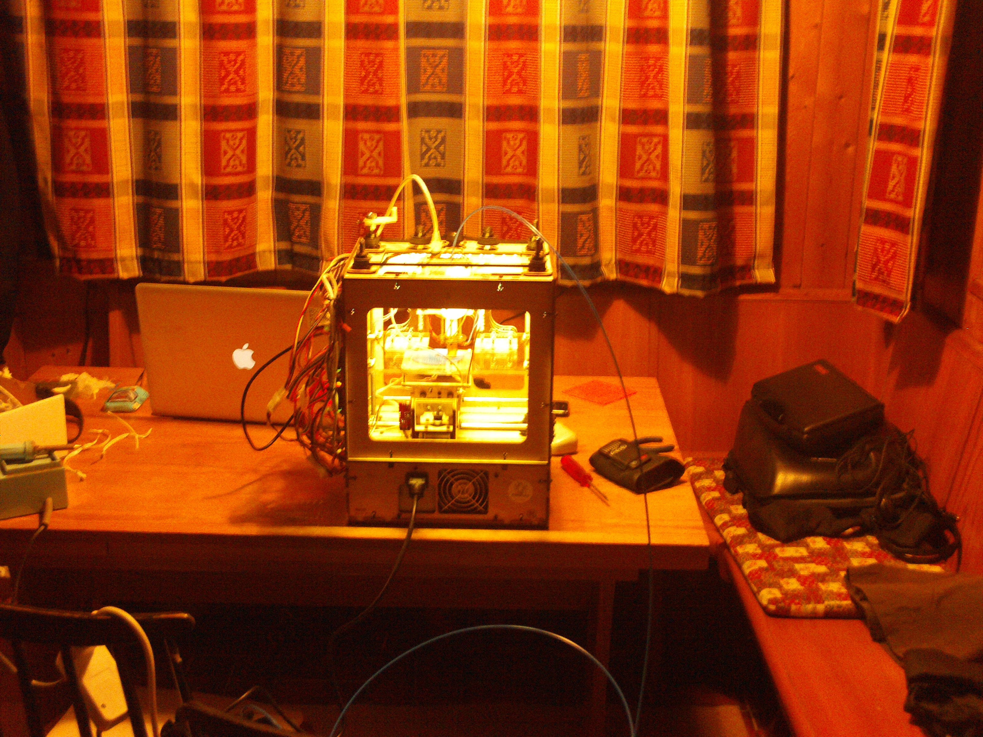
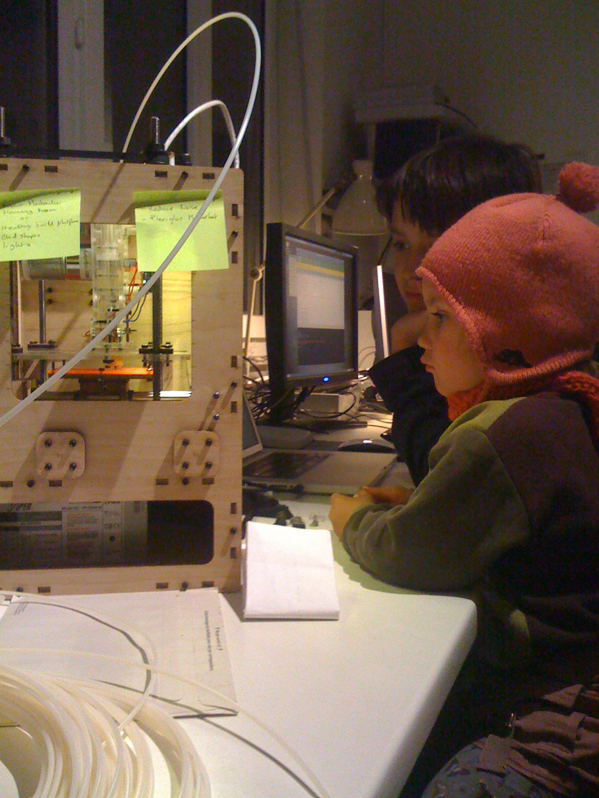
Voilà , I received a makerbot in the beginning of February. The following is the story of my adventures with this great, but at times frustrating, piece of technology.
When I ordered the printer, I was expecting a tool and not a toy. I strongly hoped that I would be able to print my own parts for bots, prototype and so on. I believe I will now be able to use it as a tool, but it took some work and tinkering to get there.
When the package arrived, I had to wait 2 more days before starting to build the machine. But then, I forgot all my duties and dove deep in the assembly for what turned out to be a long evening of happiness. I can easily relate this moment with my child memories: spending days and night with legos, mekanos and computers, where the conscience is a perfect mix of dreams and reality.
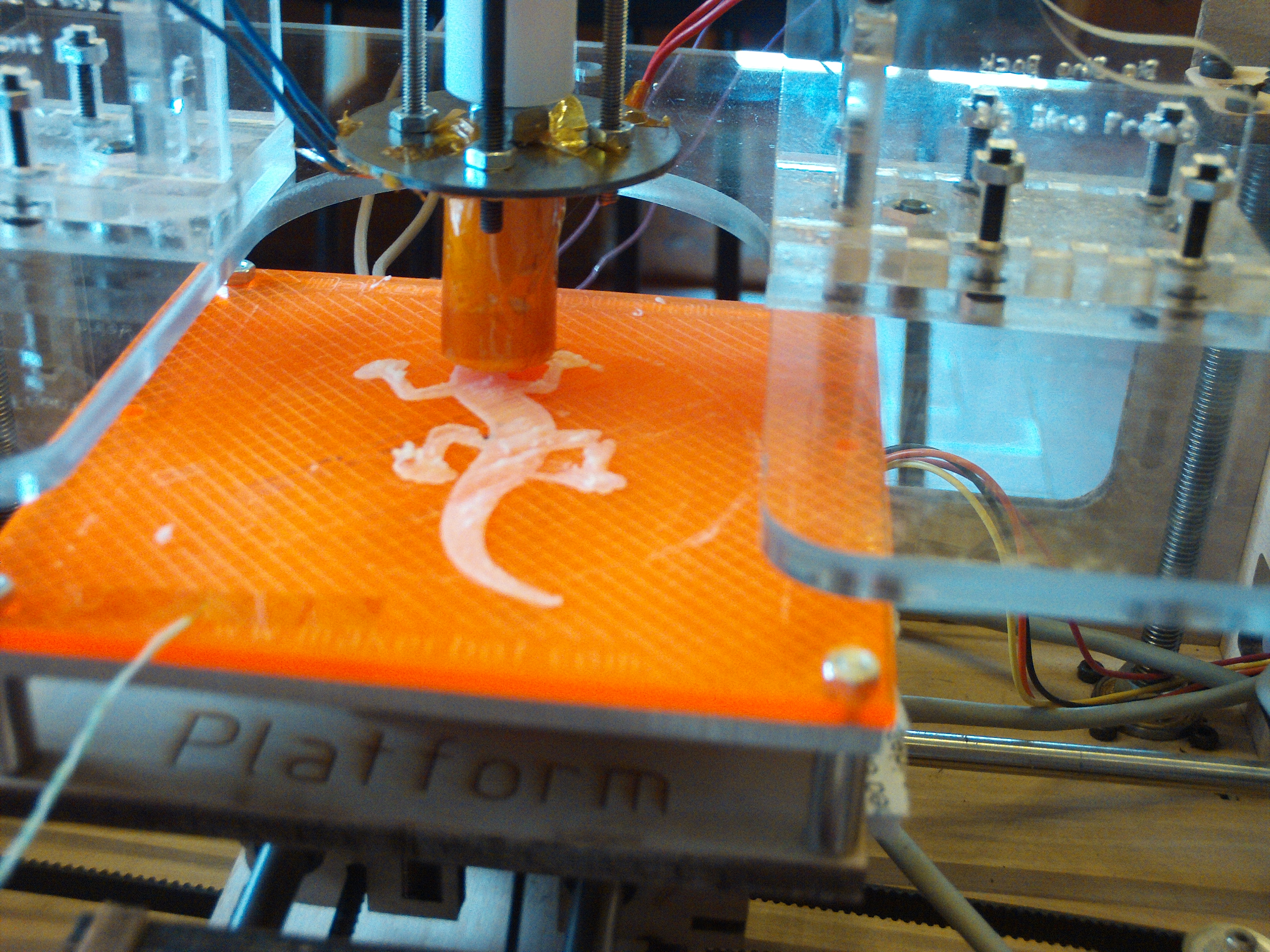
Building the printer was easy. It’s pretty well explained on wiki.makerbot.com. The parts are precise and well designed.
Except for some details with the plastruder and the inversion of two motor axis, everything worked out of the box.
However, I experienced pain with the software. Skeinforge is a complicated software, because 3D printing by extrusion is something complicated. But Skeinforge is also a bit immature and performances are not that good.
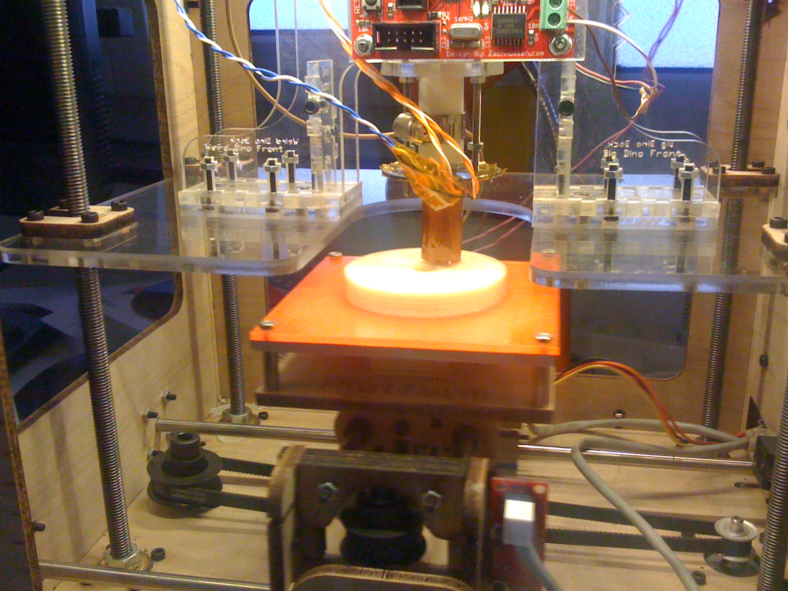
Anyways, finally I was able to print little pieces. However, when I tried larger pieces or more complicated forms, the plastruder jammed. It took me a while to understand the multiple origins of this problem:
1. the plastruder
Assembling the extruder isn’t that difficult as long as you understand what really matters !
It is well documented on the internet, but I think it’s worth telling again.
Two mechanism are fundamental : 1. the ABS filament propulsion
The force which causes the extrusion has to be powerful and constant. Makerbot industries produced a new pulley gear which improves this aspect.
It turns out after a short while that the idler bearing brike because of the excessive forces bearing on it.
To make it push ‘like a charm’ I had to check the following points twice :
– the idler pulley is stable and well aligned with the motor pulley (which is not so easy, I used spare washers)
– the motor pulley used should be the MK5 model, the new one
– washers around the idler bearing should be oriented to produce as little friction as possible
– the gad between both pulleys is tight and correct (use the calibration tool to check)
– everything is well tightened
It should be very difficult (and not recommended) to keep the filament from going forward through the pinch system.
2. the linearity of the filament’s path through the insulator to the heater barrel
When the heat is on, it happens that the PTFE insulator expands with the effect to let ABS matter leak between the insulator and the heating barrel. The more material leaks, the wider the gap grows.
When the insulator inflates it becomes impossible to extrude.
Digging the web I found two solutions :
– Using PEEK insulator instead of PTFE seams to improve durability (I haven’t tried this yet, my parts have just arrived)
– Tighten the insulator with a hose clamp (which I did on my old defunct PTFE insulator)
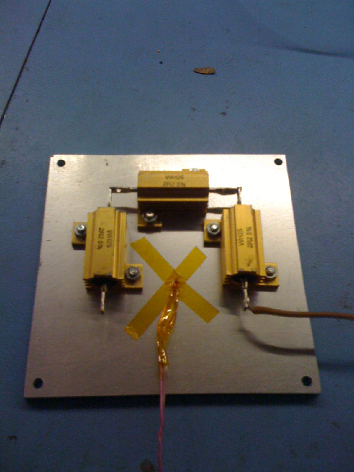
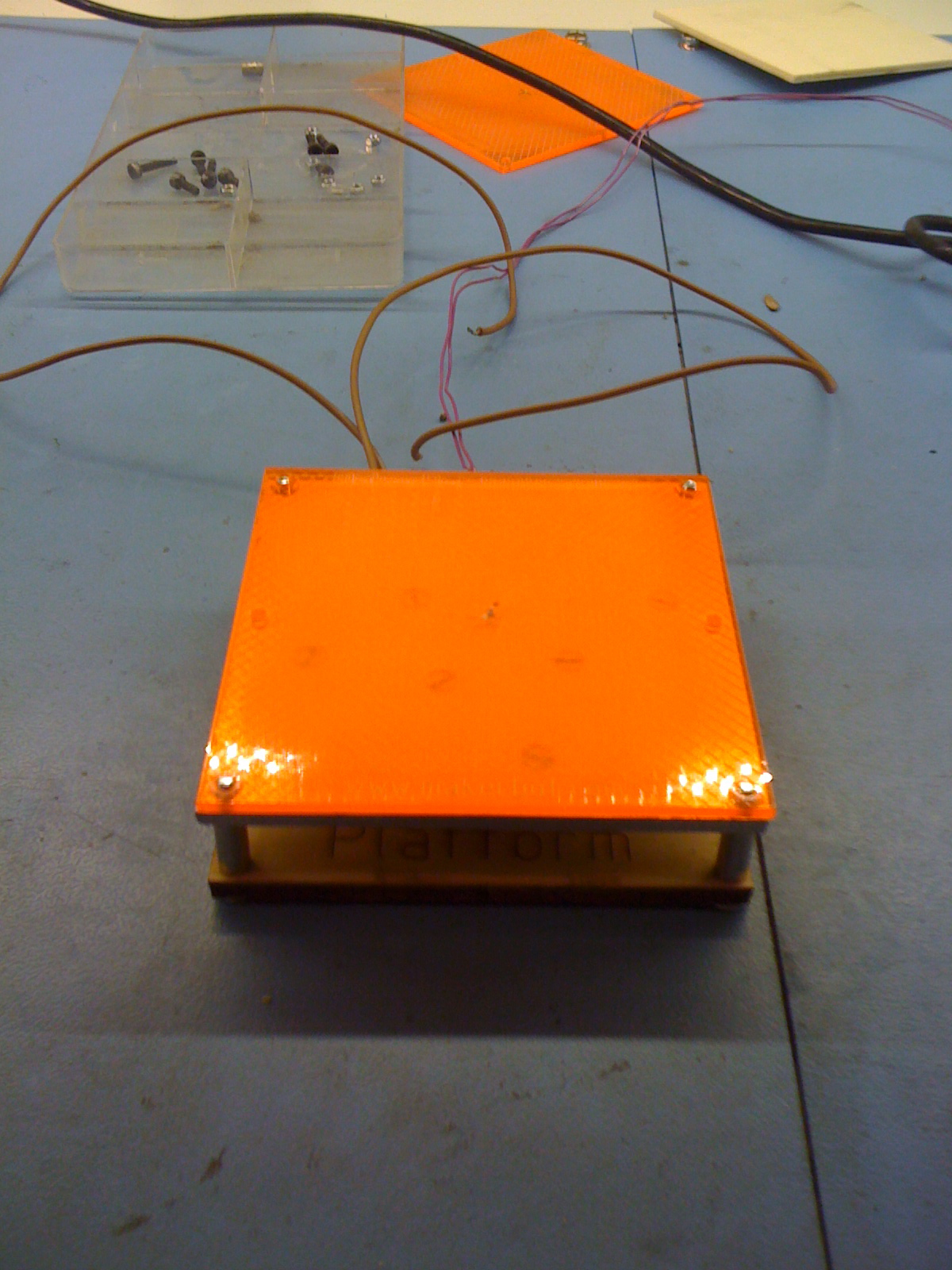
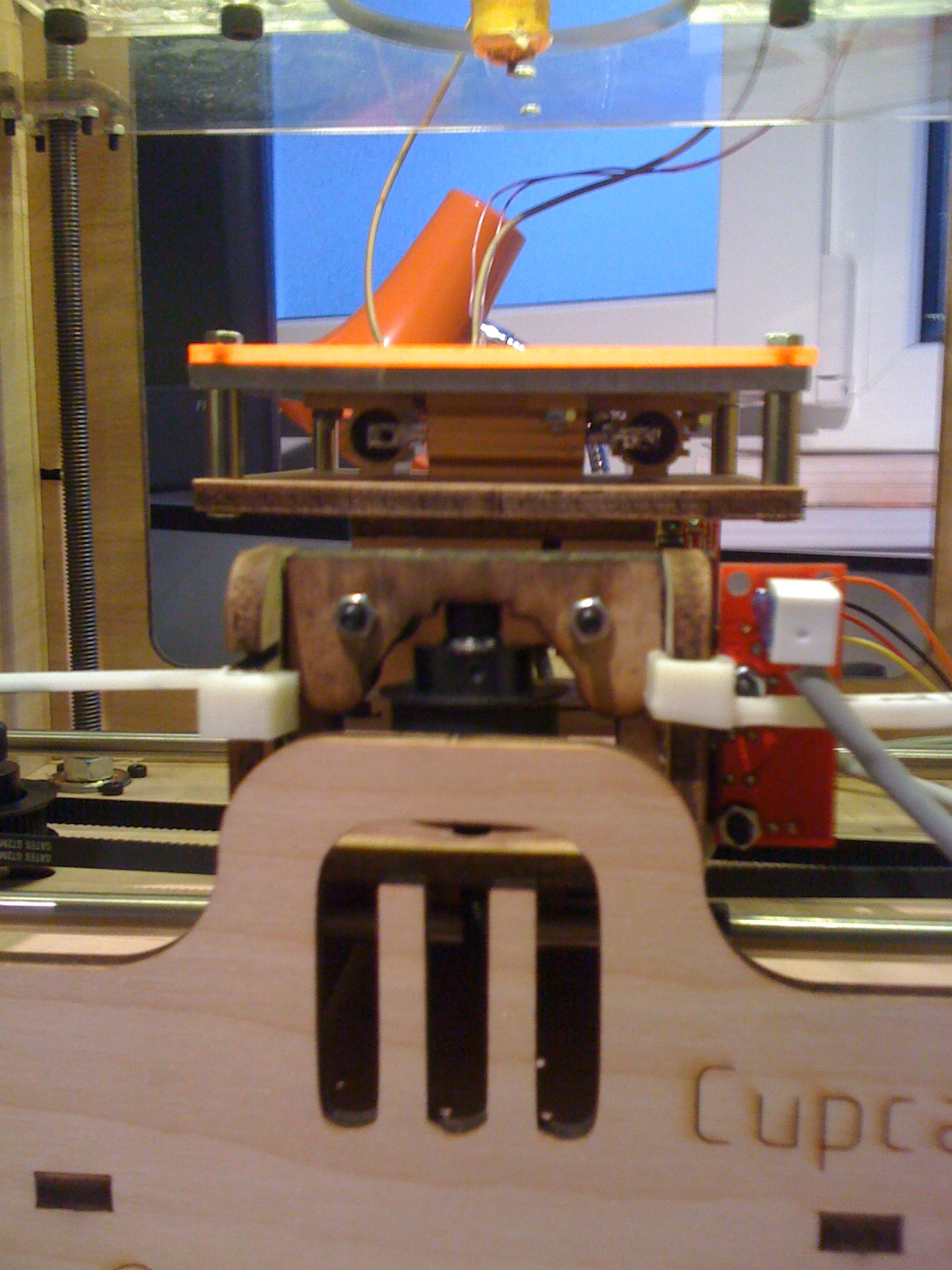
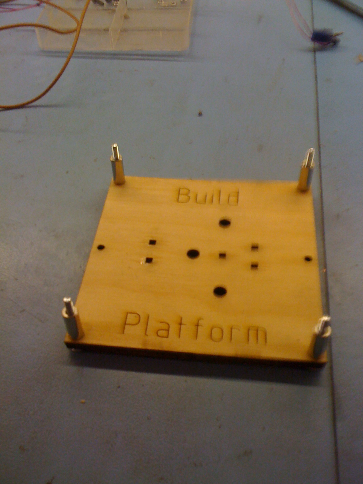
3. the heating platform
A heating platform is a good choice. Mine is made of 3 8ohm resistors setup in serial.
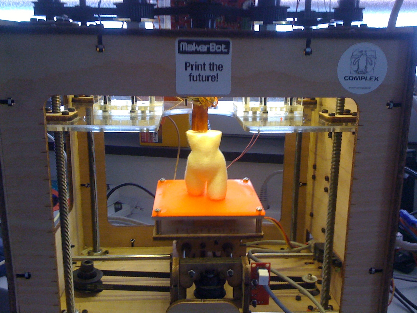
With theses two adaptations, I’ve been able to print almost everything.
ReplicatorG
Working with skeinforge’s configuration was a bad adventure. Fighting with parameters and struggling with weak performances isn’t easy at all.
Hopefully the new ReplicatorG can hide all those details for beginners and grumpy guys like me.
Tonight is the first time I could print in peace and reliably, without worries, which explains my motivation in writing this post. I’m happy and looking forward to finding lots of real use for my printer. Thanks to makerbot industries and thanks to all the makerbot owners who helped me find a solution.
I made some progress with the pololu tracking and control project.
To allow for better control, I updated the communication protocol between the desktop program and the robot. The previous version supported a minimal set of commands (stop, forwards, spin left, spin right). This set has been replaced by a tuple of values directly controlling the speed of the left and right motors. This allows us to write a more “ambitious” target following algorithm.
The new heuristic is in two steps, speed and direction. We first determine the distance between the tracked robot and the target, and set the speed component as a proportion to distance (close = slow, far = fast). The direction is calculated in a similar fashion: we turn in the direction of the target, the bigger the angle difference between the current heading of the 3pi and the target, the stronger the turn. This remains a simple algorithm, but I a kind of like the behavior. There is more life to it. The following video illustrates (the white dot represents the position of target, the orange dot represents the position of the tracked 3pi robot).
I was recently working on some boid like procedural animations and I was thinking it would be fun to transpose such a system in the physical space. Theo recently received a collection of 5 pololu 3pi robots, and I decided they would be ideal candidates for such a project.
The 3pi pololu robots are fairly simple, so I figured it would be easier to consider the robots as brainless and blind particles under the control of an all-seeing “smart” desktop computer.
The first problem was remote communication with the 3pi. Thankfully, Theo was kind enough to mount an xbee module on one of the bots. This allows remote communication via a serial port abstraction.
The second problem was vision, the desktop controller needs to know the position of the 3pi. As I wanted to create a test environment quickly I fired up CCV instead of written custom tracking code. This is an open source tracker usually used for multitouch surfaces.
I thought it would be interesting to track the 3pi with Infrared light, this would allow for a overhead projection to be added later without influencing the tracking. I used an IR sensitive ps3 eye webcam and Theo added an infrared led to the 3pi to make it visible to the camera (it’s the led on top of the mast on the 3pi picture). The setup was ready to track and send the position of the 3pi to the main desktop program. Now that I knew the position of the 3pi, it was time to make it find and move to a new arbitrary position (target).
For a first test, I opted for a very naive strategy. The situation is the following:
1. we know the position of the 3pi via tracking but not its orientation (visually tracking the orientation is too big of a problem for this first test).
2. we can control the motors of the 3pi, make it move forwards and turn, but we can’t tell it to move or turn a known distance (for instance you can’t tell it to turn 30 degrees).
However, if we tell the bot to move forwards, and we track the movement, we get a new position, which we can compare to the starting position and transpose as a vector, and now we have a direction.
The next step was to decide for a simple vocabulary of movements for the 3pi. I decided that it could either be moving forwards, or spinning to the right, or spinning to the left or, finally, it could be immobile. The heuristic is then quite simple:
1. move forwards
2. are we close enough to the target to be considered the final position?
if yes
stop all done.
else
are we getting closer to the target?
if yes
continue forwards
else
decide if target is to the left or to the right of 3pi and spin in the corresponding direction, then goto 1
Granted this is very naive, but fine for a proof of concept stage.
I used openframeworks to read the tracking information and to communicate serially (xbee) with the 3pi.
You can see the first result in the following video. On the screen, the white dot represents the target and the blue dot is the tracked position of the 3pi.
As you can see the basic system is in place, but there is still a lot of work to get a more fluid experience : )