Makerbot power consumption

Because I think to power a Makerbot from a car battery, I spend a little while checking the power consumption of a Makerbot.

The main board connector feed the main logic, the plastruder and the heated platform, while the hard drive connectors feed motors and leds.

I used an old ATX connectors and made four groups of wires : 3v3, 5v, 12v and ground.
The remaining wires (5VSB, /PS_ON, PWR_OK, -12v and -5v) where directly connected to the main ATX power supply.
I did the same with hard drive connectors, I disconnected 5v, 12v and ground.
Then I plugged not less than 5 “multimeters” between each power source and ground to record all different current consumption.

So I wrote this sheet :

Voltage Average Maximum
MB 3v3 very few very few
MB 5v 200mA 350mA
MB 12v 2700mA 3500mA
HD 5v 30mA 50mA
HD 12v 1000mA 1700mA

The average power consumption of a makerbot with heating platform seams to be around 70W and the maximum power consumption around 85W. Differences may apply due to the custom configuration, it’s just an overview.

My custom heating platform is made of three 2.2Ω resistor in serial on a 3mm aluminum plate.

RECYCLING: a spoon against XDCAM Transfert

Tonight a friend came with her brand new Mac and a lot of files to import using XDCAM Transfert.
It seams that this software was made by tired developers, so we had to generate previews on every clip before importing.
Well, the real problem isn’t that you have to select the folder, but the fact that you have wait about one second for previews generation (no, there is no “group function”).

With about 3’500 folder, we would have been quickly mad.

And of course, moving all files in one folder isn’t possible, because they already are sorted.
There is probably many other (programmatic and smarter) solutions, but the punk-ier still is the funn-ier, no ?

So my solution is to recycle an old project, writing this post and going for a nice diner, while the mechanism goes by it-self…

PS: I guess it’s a good way to test keyboards…

#include 

Servo servo;

int servo_pin = 9;

void setup ()
{	
  servo.attach(servo_pin);
  Serial.begin(57600);
  Serial.println ("Finished setup\n");
}

void loop ()
{
  servo.write(115);
  delay(250);
  servo.write(80);
  delay (1000);
}

Makerbot, long story short

Voilà, I received a makerbot in the beginning of February. The following is the story of my adventures with this great, but at times frustrating, piece of technology.

When I ordered the printer, I was expecting a tool and not a toy. I strongly hoped that I would be able to print my own parts for bots, prototype and so on. I believe I will now be able to use it as a tool, but it took some work and tinkering to get there.

When the package arrived, I had to wait 2 more days before starting to build the machine. But then, I forgot all my duties and dove deep in the assembly for what turned out to be a long evening of happiness. I can easily relate this moment with my child memories: spending days and night with legos, mekanos and computers, where the conscience is a perfect mix of dreams and reality.

Building the printer was easy. It’s pretty well explained on wiki.makerbot.com. The parts are precise and well designed.
Except for some details with the plastruder and the inversion of two motor axis, everything worked out of the box.
However, I experienced pain with the software. Skeinforge is a complicated software, because 3D printing by extrusion is something complicated. But Skeinforge is also a bit immature and performances are not that good.

Anyways, finally I was able to print little pieces. However, when I tried larger pieces or more complicated forms, the plastruder jammed. It took me a while to understand the multiple origins of this problem:

1. the plastruder

Assembling the extruder isn’t that difficult as long as you understand what really matters !
It is well documented on the internet, but I think it’s worth telling again.
Two mechanism are fundamental :
1. the ABS filament propulsion
The force which causes the extrusion has to be powerful and constant. Makerbot industries produced a new pulley gear which improves this aspect.
It turns out after a short while that the idler bearing brike because of the excessive forces bearing on it.
To make it push ‘like a charm’ I had to check the following points twice :
– the idler pulley is stable and well aligned with the motor pulley (which is not so easy, I used spare washers)
– the motor pulley used should be the MK5 model, the new one
– washers around the idler bearing should be oriented to produce as little friction as possible
– the gad between both pulleys is tight and correct (use the calibration tool to check)
– everything is well tightened

It should be very difficult (and not recommended) to keep the filament from going forward through the pinch system.

2. the linearity of the filament’s path through the insulator to the heater barrel
When the heat is on, it happens that the PTFE insulator expands with the effect to let ABS matter leak between the insulator and the heating barrel. The more material leaks, the wider the gap grows.
When the insulator inflates it becomes impossible to extrude.
Digging the web I found two solutions :
– Using PEEK insulator instead of PTFE seams to improve durability (I haven’t tried this yet, my parts have just arrived)
– Tighten the insulator with a hose clamp (which I did on my old defunct PTFE insulator)

3. the heating platform

A heating platform is a good choice. Mine is made of 3 8ohm resistors setup in serial.

With theses two adaptations, I’ve been able to print almost everything.

ReplicatorG

Working with skeinforge’s configuration was a bad adventure. Fighting with parameters and struggling with weak performances isn’t easy at all.
Hopefully the new ReplicatorG can hide all those details for beginners and grumpy guys like me.

Tonight is the first time I could print in peace and reliably, without worries, which explains my motivation in writing this post. I’m happy and looking forward to finding lots of real use for my printer. Thanks to makerbot industries and thanks to all the makerbot owners who helped me find a solution.

links

STL-> gcode improvement witch CUDA : http://pleasantsoftware.com/developer/3d/
Interesting experiments : http://hydraraptor.blogspot.com/
hose clamp solution on makerbot blog : http://blog.makerbot.com/2010/07/14/barriers-barrels-ptfe-oh-my/
hose clamp solution on makerbot forums : http://wiki.makerbot.com/forum/t-250421

pololu 3pi ir tracking and control V2

I made some progress with the pololu tracking and control project.

To allow for better control, I updated the communication protocol between the desktop program and the robot. The previous version supported a minimal set of commands (stop, forwards, spin left, spin right). This set has been replaced by a tuple of values directly controlling the speed of the left and right motors. This allows us to write a more “ambitious” target following algorithm.

The new heuristic is in two steps, speed and direction. We first determine the distance between the tracked robot and the target, and set the speed component as a proportion to distance (close = slow, far = fast). The direction is calculated in a similar fashion: we turn in the direction of the target, the bigger the angle difference between the current heading of the 3pi and the target, the stronger the turn. This remains a simple algorithm, but I a kind of like the behavior. There is more life to it. The following video illustrates (the white dot represents the position of target, the orange dot represents the position of the tracked 3pi robot).

3pi pololu robot controlled via ir tracking: second test from david hodgetts on Vimeo.

pololu 3pi robot controlled via computer vision: first test

I was recently working on some boid like procedural animations and I was thinking it would be fun to transpose such a system in the physical space. Theo recently received a collection of 5 pololu 3pi robots, and I decided they would be ideal candidates for such a project.

The 3pi pololu robots are fairly simple, so I figured it would be easier to consider the robots as brainless and blind particles under the control of an all-seeing “smart” desktop computer.

The first problem was remote communication with the 3pi. Thankfully, Theo was kind enough to mount an xbee module on one of the bots. This allows remote communication via a serial port abstraction.

The second problem was vision, the desktop controller needs to know the position of the 3pi. As I wanted to create a test environment quickly I fired up CCV instead of written custom tracking code. This is an open source tracker usually used for multitouch surfaces.

I thought it would be interesting to track the 3pi with Infrared light, this would allow for a overhead projection to be added later without influencing the tracking. I used an IR sensitive ps3 eye webcam and Theo added an infrared led to the 3pi to make it visible to the camera (it’s the led on top of the mast on the 3pi picture). The setup was ready to track and send the position of the 3pi to the main desktop program. Now that I knew the position of the 3pi, it was time to make it find and move to a new arbitrary position (target).

For a first test, I opted for a very naive strategy. The situation is the following:
1. we know the position of the 3pi via tracking but not its orientation (visually tracking the orientation is too big of a problem for this first test).
2. we can control the motors of the 3pi, make it move forwards and turn, but we can’t tell it to move or turn a known distance (for instance you can’t tell it to turn 30 degrees).

However, if we tell the bot to move forwards, and we track the movement, we get a new position, which we can compare to the starting position and transpose as a vector, and now we have a direction.

The next step was to decide for a simple vocabulary of movements for the 3pi. I decided that it could either be moving forwards, or spinning to the right, or spinning to the left or, finally, it could be immobile. The heuristic is then quite simple:

1. move forwards

2. are we close enough to the target to be considered the final position?
if yes
stop all done.
else
are we getting closer to the target?
if yes
continue forwards
else
decide if target is to the left or to the right of 3pi and spin in the corresponding direction, then goto 1

Granted this is very naive, but fine for a proof of concept stage.
I used openframeworks to read the tracking information and to communicate serially (xbee) with the 3pi.

You can see the first result in the following video. On the screen, the white dot represents the target and the blue dot is the tracked position of the 3pi.

As you can see the basic system is in place, but there is still a lot of work to get a more fluid experience : )

3D printing Thursday

OK.
You don’t know it yet because I haven’t bloged it, but I received a nice cupcake from Makerbot industries yesterday. The box is already built and it prints pretty well.
This post proudly announces the 3D printing thursday.
I believe people who don’t have access to 3D printer but have ideas that need to be solidified should come and see the revolution in motion.

So, it’s every thursday from tomorrow to infinity, Complex ai, 5 Rue des Maraîchers, 1205 Genève, Suisse.
It starts at 19:00
If you want to print stuff (I hope so), you are invited to come with .stl file (USB, internet, whatever) instead of just ideas. I don’t know much about 3D and I’m not able to realize phantasms with modeling software. So please, bring them with you otherwise than in your head. Make it REAL, tangible, touchable, usable !

fire to the makerbot !“. Many thanks to MakerBot Industries to 3D printing and happiness that comes along.

See ya.

chic chic chic!

de la bonne stoff hier soir à l’Usine pour le workshop Arduino! après une short intro pour démystifier l’Arduino et prouver que même ma Grand-Mère pouvait faire blink, on est passé au vif du sujet: tout le monde a commencé à fouiller dans les caisses à trésors de Théo à la recherche d’un vieux robot ou d’un pack de leds.

photo

et là on a vu plein de belle choses se passer. tellement bien de voir qu’à chaque nouveau tour de table, chacun(e) a ajouté un nouveau truc à son circuit et que petit à petit notre armée de hackers allait conquérir le monde électronique, une led après l’autre… as said, “resistance is futile” and we WILL conquer Geneva, one Arduino after the other!

photo-1

on remet ça dimanche prochain, allez le crier sur les toits!!!!

Resistance is futile @ le Zoo/Usine – 8 et 15 novembre 09

flyer

Lire ce billet dans la langue de Voltaire.
Read this post in Shakespeare’s tongue.


Le spleen du dimanche d’automne n’est pas une fatalité, venez découvrir et apprendre à utiliser les merveilles électriques de la plateforme arduino avec le allstar cast de modprobe.ch. A la soudure et robotique Theo Reichel, au platine du code Monsieur Java en personne Renaud Richardet, acompagné en exclusivité mondiale par le über-guru du C Philippe Vaucher en personne, finalement au support moral on trouvera le pousseur de pixel David Hodgetts. Le workshop s’adresse à un large public, artiste et bricoleur du dimanche bienvenu.

Hard

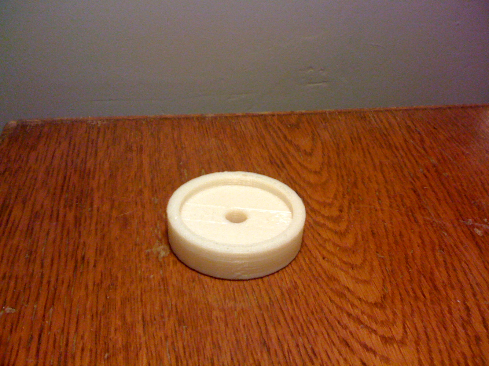
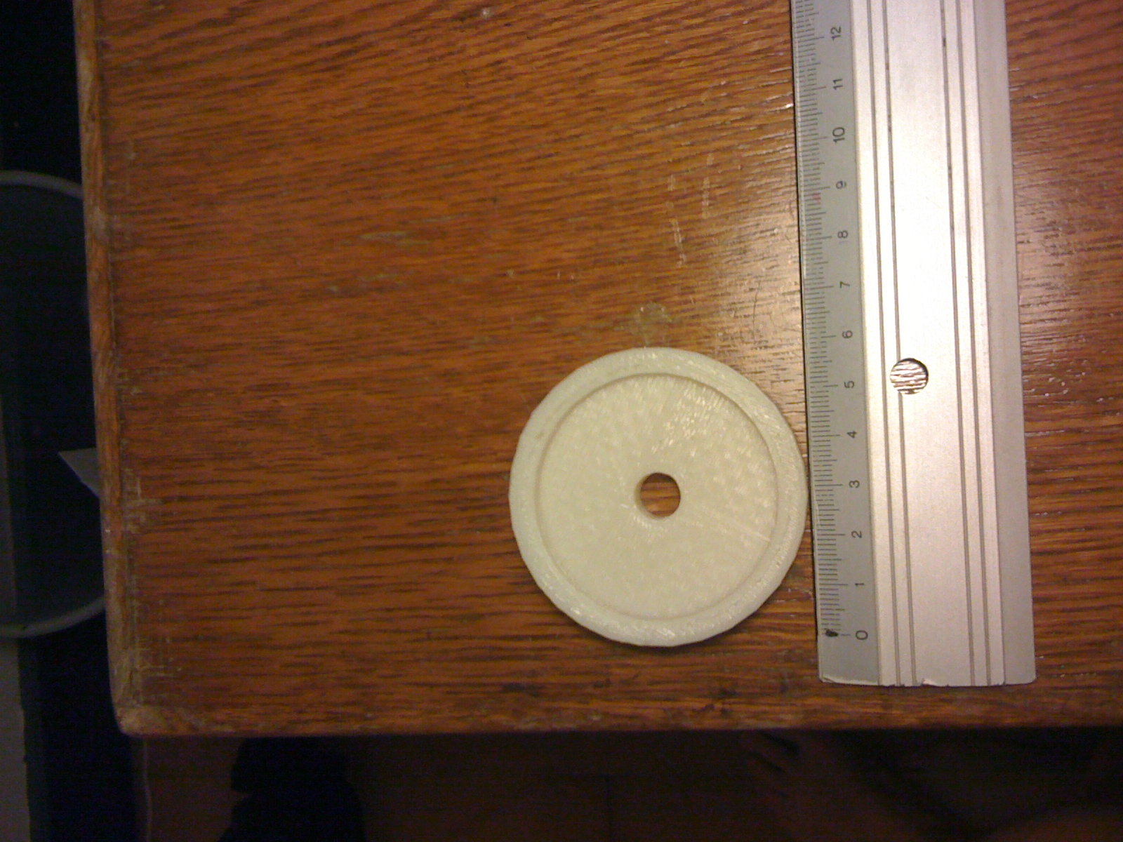
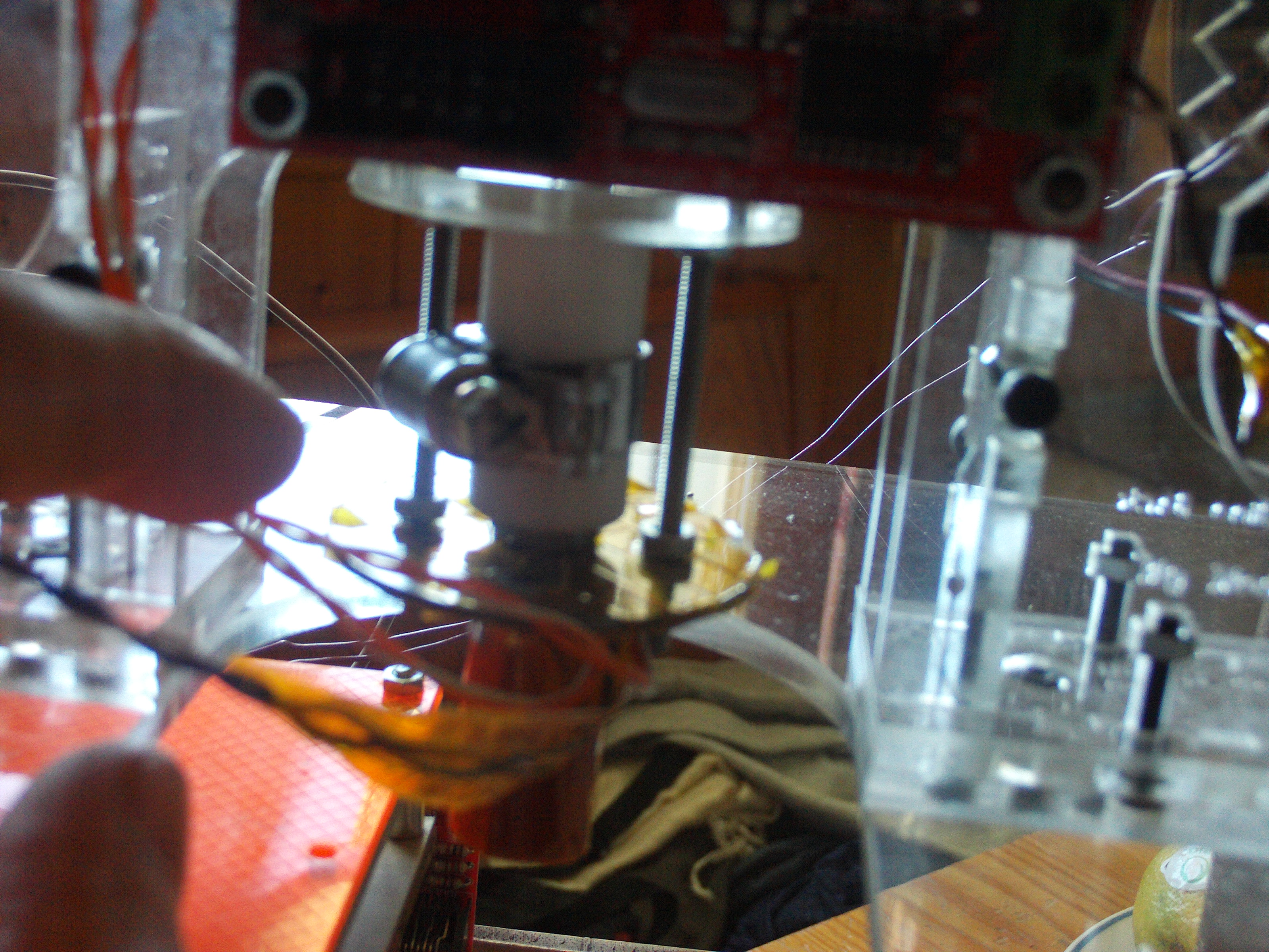
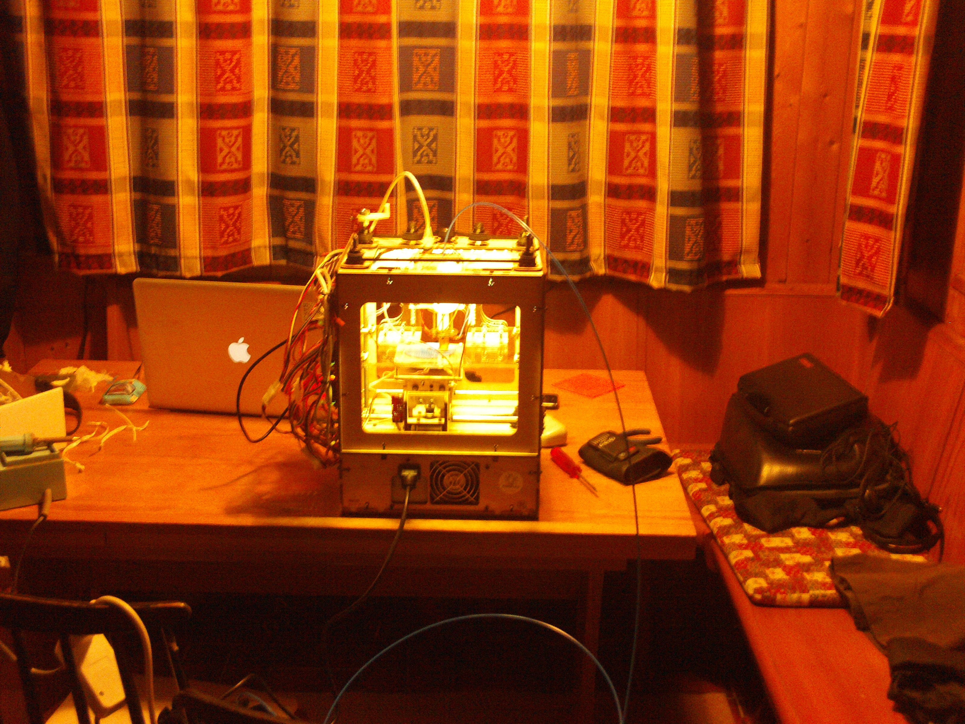
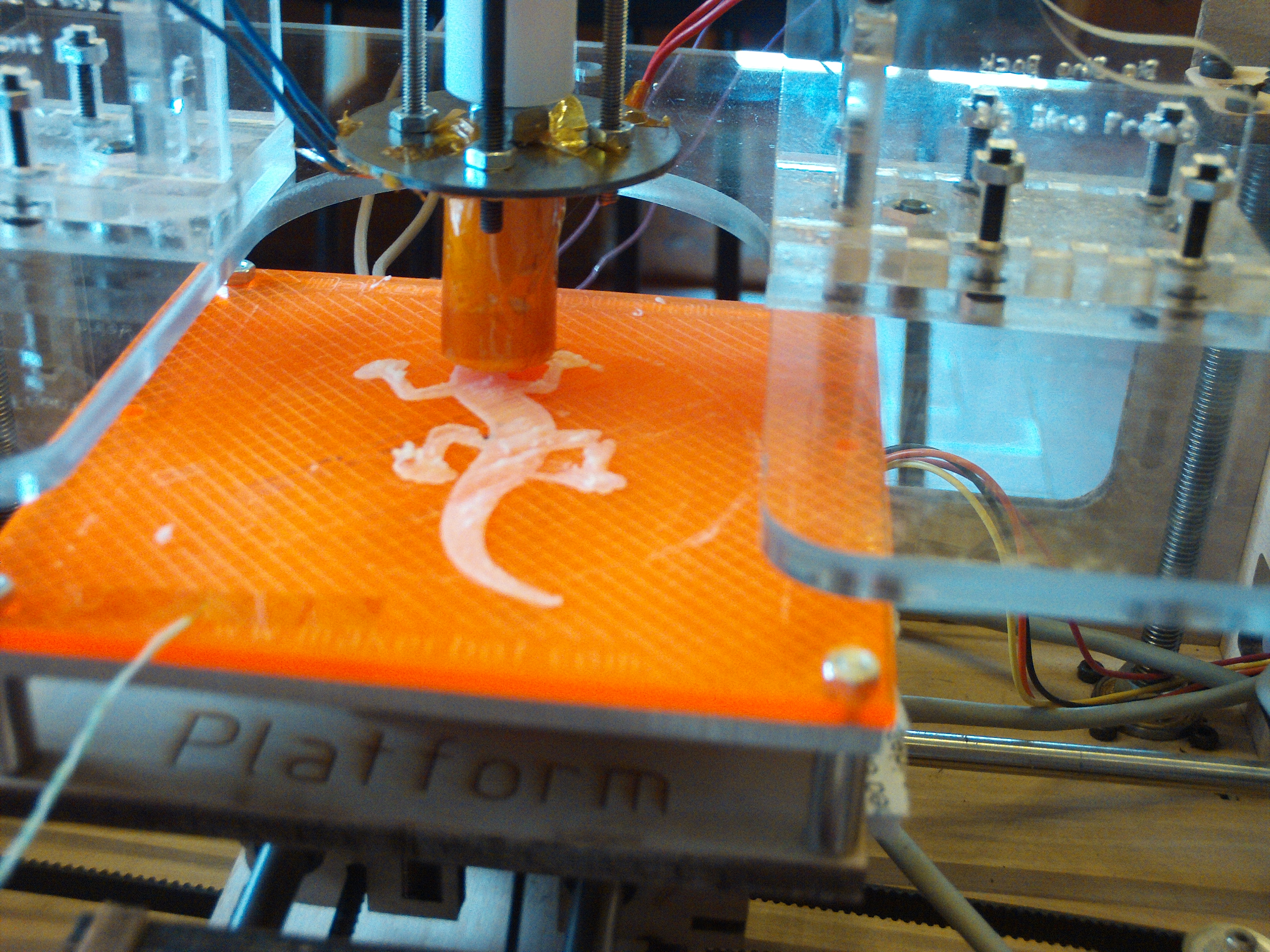
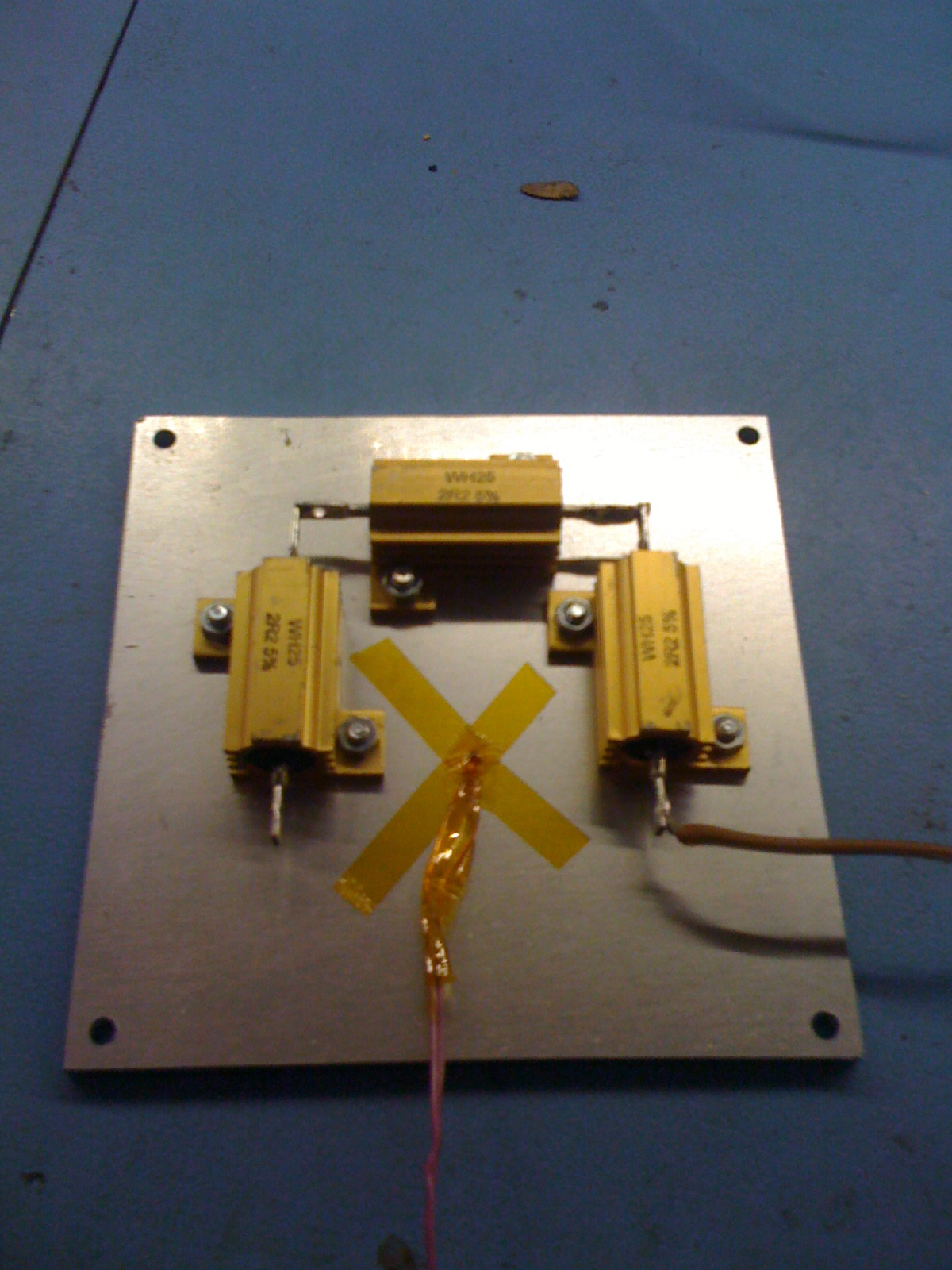
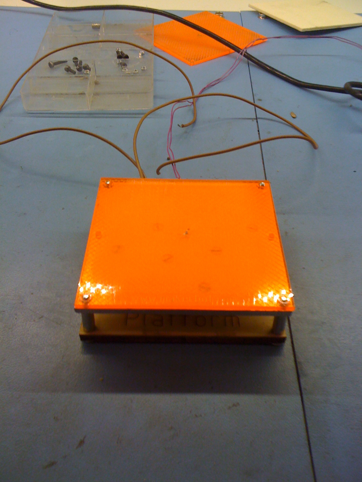
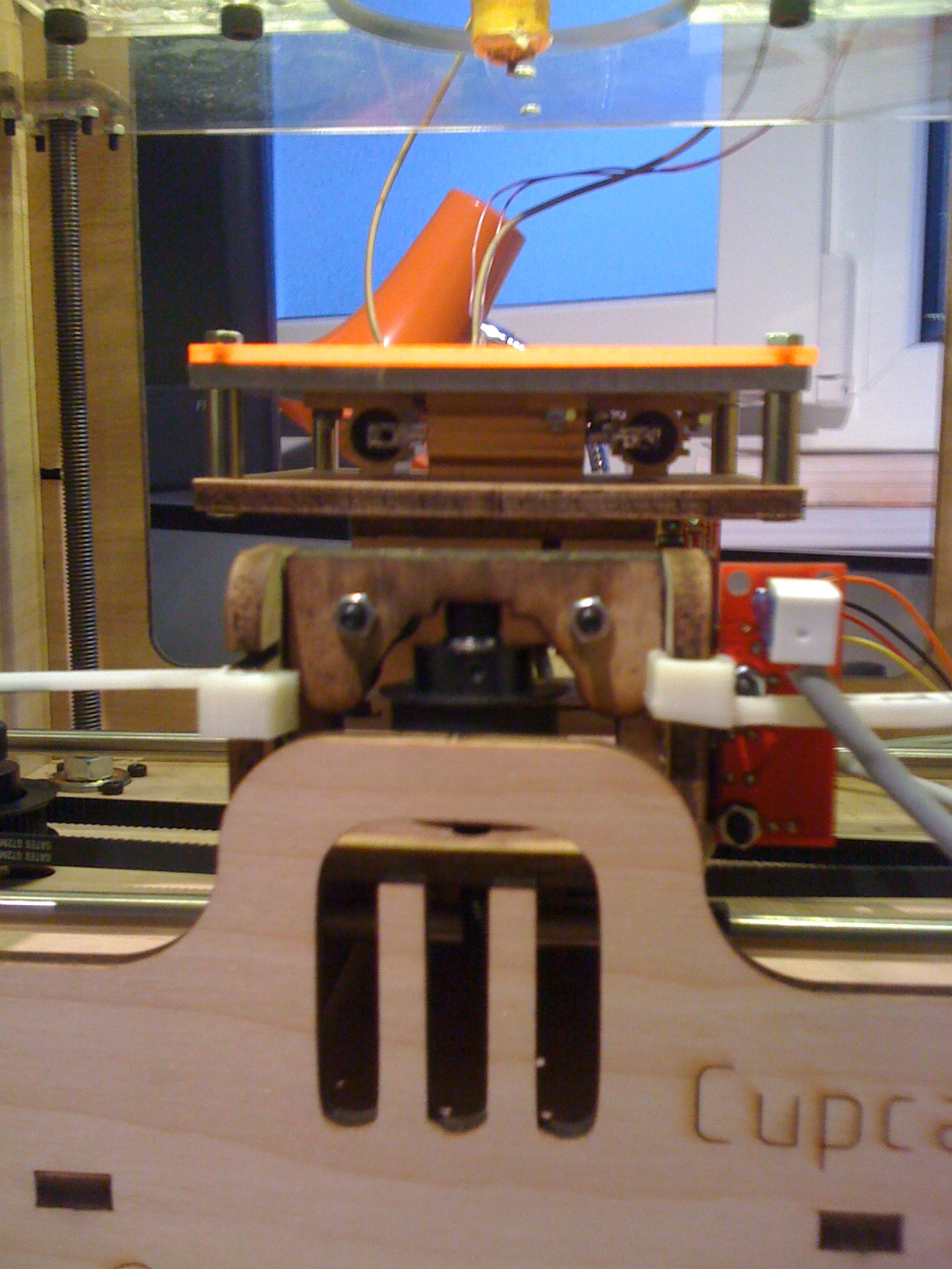
Pour suivre le workshop dans les meilleures conditions, il faut amener un laptop (mac linux ou windows) et un kit arduino. Pour ceux qui le désirent, l’usine a 16 kits starter arduino à vendre. Il est évidement également possible de venir avec son propre matos tant qu’il s’agit de la même plateforme (micro-contrôleurs ATMEGA8-168-328). Sur place, vous trouverez plein de composants marrants: moteurs linéaire ou pas à pas, servos, LED puissante et moins puissantes, drivers de puissance, transistors, ICs en tout genre, bière etc. Dans le bordel et plus spécifiquement pour arduinos et artistes, module son (wave), module de puissance pour mécaniques, plaque de prototypage à souder, module Xbee, etc.

Thunes

Entrée : 10 balles Kit arduino (optionnel) : 50 balles (Arduino Duemilanove 328, breadboard, composants divers, fils, voir ici pour le détail)

Lieu

Le zoo de l’usine
4 pl. des volontaires
1204 Genève
www.lezoo.ch

Programme

Samedi 7 novembre 2009, 10h-12h

Des-puces-lage : Balade sur la plaine de plainpalais à la recherche de matériel électronique pour occuper le workshop. Participants les bienvenus.
Rendez-vous à 10h00 à la roulotte (46.197929, 6.139324)

Dimanche 8 novembre 2009, 16h-20h

Premier workshop : introduction à la plateforme arduino
En gros :
30min intro, qu’est-ce que l’arduino, exemple d’utilisation.
30min installation sur les machines et clignotement d’une LED
1h presentation de projets connus
1h mini-workshop pour se faire les dents sur la plateforme
1h presentation de project modprobe et potes.

Samedi 14 novembre 2009, 10h-12h

Marché aux puces: Deuxième balade plus ciblée : circuit-bending, méchanique, électronique de puissance, etc.
Rendez-vous à 10h00 à la roulotte (46.197929, 6.139324)

Dimanche 15 novembre 2009, 16h-20h

Second workshop : Réalisation d’un projet arduino, présentation de projets hardcores
1h, présentation de projets poussés, de quoi faire rêver
3h, workshops les mains déliées avec le soutiens d’une équipe de 5 gars compétents, dans le domaine de l’électronique, de l’informatique et du lard.

Formulaire d’inscription

Nous avons a disposition 16 kit “Budget pack” d’adafruit industries. Pour réserver votre kit ou vous inscrire au workshop, merci de remplir le formulaire ci-dessous.


Resistance is futile @ the Zoo/Usine Geneva november 8 and 15 2009

No need to suffer from autumnal sunday spleen anymore… Come discover the electrical wonders of the arduino platform with the allstar modprobe crew: on the soldering iron and general robotics expert, Theo Reichel. Spinning and grooving, the one and only Mr Java, Renaud Richard, exceptionally assisted by the world acclaimed all time C über geek, Phillipe Vaucher. Finally, on general moral support, David Hodgetts the pixel pusher. The workshop is open to all. Artists and sunday do-it-yourselvers welcome !

Hard

To follow the workshop in the best consitions, you will need a laptop (mac, linux or win) and an arduino kit. Le zoo-usine has 16 arduino starter kits to sell for interested participants. Of course, it is also possible to come with your own chips as long as they are based on the ATMEGA8-168-328 family. Plenty of fun components will be available to play with: motors, leds, sensors, ICs, wave modules, etc.

Finance

Entry : 10 chf Arduino kit arduino (optional) : 50 chf (Arduino Duemilanove 328, breadboard see here for details).

Location

Le zoo de l’usine
4 pl. des volontaires
1204 Genève
www.lezoo.ch

Language of the workshop

The workshop is in french.
But if there is subscribers speaking only english, the workshop will be translated in live for them.

Program

Saturday november 7 2009, 10h-12h

Object-Hunting: Stroll around the plaine of plainpalais’ s flea market on the look for electronic treasures. Workshop participants welcome.
Meeting point 10h00 @ “la roulotte” (46.197929, 6.139324)

Sunday november 8, 16h-20h

first workshop : introduction to the arduino platfom
30min intro, what is arduino , real world examples.
30min arduino hard and soft install and blinking led test. 1h case studies.
1h applied arduino examples.
1h modprobe project presentation.

Saturday november 14 2009, 10h-12h

Flea-market: The second stroll : circuit-bending, mechanics, power electronics, etc.
Meeting point 10h00 @ “la roulotte” (46.197929, 6.139324)

Sunday november 15 2009, 16h-20h

Second workshop : warm-up: production of an arduino project.
1h presentation of crazy hardcore skills projects
3h free-form workshop

Enroll here

We have 16″Budget pack” kits from adafruit industries. To order an arduino kit or to to book a seat for the workshop please fill in the following form.


a spoon to feed, two prototypes

For Ida.

Well, this project seemed to be so easy, but it so wasn’t.
The description is the following : “Before dying I had to make an apparel able to transmit touch or pressure sensation through the distance.”
The purpose of such an apparel is obvious, trying to reduce body distance and allowing hand collision in spite of kilometers.
There are some kind of relationships who need more than the spiritual belief of “we keep in touch” when contact isn’t possible.

So why the spoon ?
The symbolic of the spoon used to feed is strong. No need to define what sort of emotions have been transmitted through our first spoon of food. No need to express the feelings we had towards those who used to feed our mouth. We all have a different kinds, but probably strong for everyone.

Feeding is the responsible act for keeping alive.
(Alimenter est l’act responsable de maintenir en vie)

The spoon is a cold iron tool. With at least one curve and a nest for something liquid, difficult to keep by definition. It’s an agile shape for our clumsy hands, and it does the job.
Spoon by its shape, size and material is also an erotic object. Not to feed we agree, fork is more romantic, but for imagination.
As I was born in a protestant city, I’ll let you figure out what you can do and how to play around with a spoon. Some people could be shocked, and It’s really not my kind, oh no !
(the truth : I keep alive the dream and wait patiently for a receptive body, no need to spread desire if I release the code and plans, no?)

Somehow, the spoon is for food what this prototype is for the relationship, an artifact of love.
A new tool to feed the relationship.

Code and electronic will come later.
Right now, what matters is : Arduino, modified servo, spoon, capacitive meter.

img_0608

img_0610

Les premiers pas de mon moteur à pas.

Avec tout ces moteurs récupérés, il fallait bien que j’essaye d’en faire marcher un.
J’ai pas fini de faire les poubelles, mais pour l’instant c’est dans de vieux scanner que j’ai trouvé les moteurs par-à-pas les plus puissants…

Nous avons réussi.

6 moteurs sur 7 récupérés sont des bipolaires, je les contrôle depuis l’ALIX, via le port parallèle, et un chip L293 avec un bout de code ruby. (lequel sera publié dans une màj de cette page prochainement)
Il m’a fallu 4 fils et une séquence précise pour piloter le moteur.

Avec les deux seuls moteur identiques (et les deux seuls achetés, 9.- ça va) j’ai construit une petite voiture. J’étudie le moyen d’en faire un véhicule totalement autonome (et pourquoi pas asservis), avec l’ALIX ou une WRAP.

Les premiers pas… le premier tour.

L’Analyseur logique pour tester mon code. (via GPIO)

La voiture tourne.

La voiture avance.

11052007006.jpg
20052007001.jpg
11052007007.jpg

Un grand merci à ceux qui mon appris, assisté, suivit. Et à ceux qui ont partagé ma joie.
Quentin, Jonas, Eric, Loraine, …